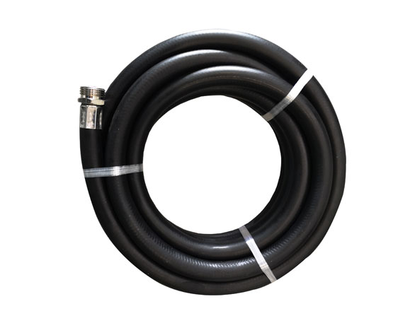
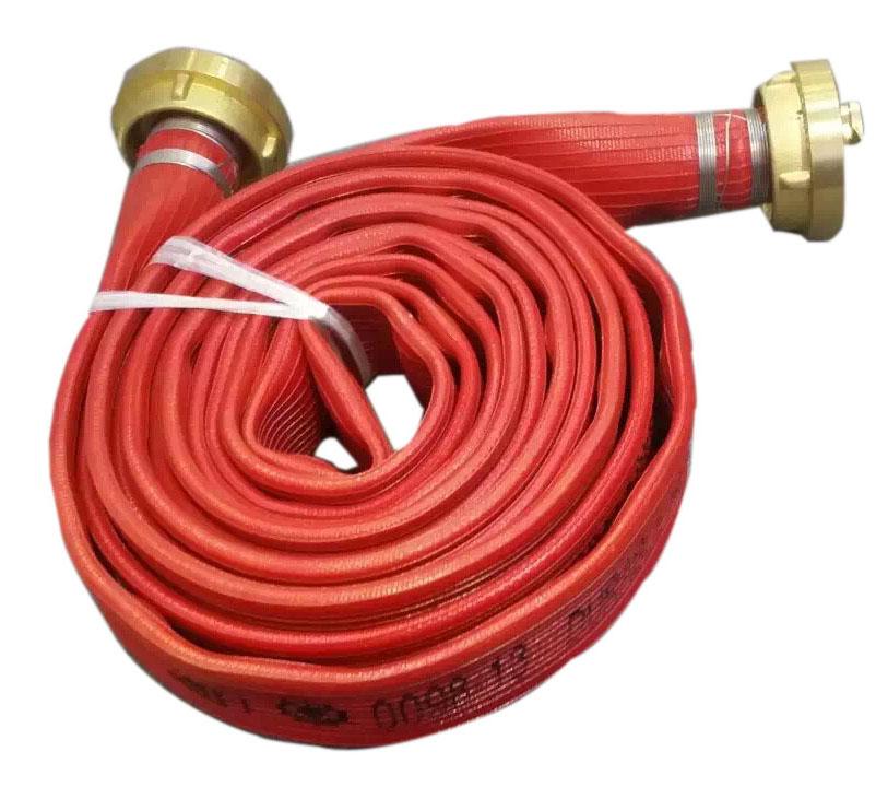
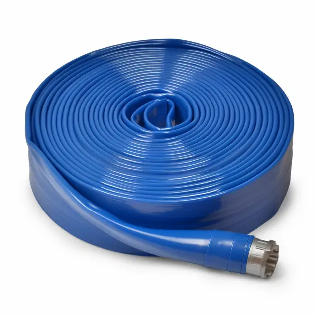
Hose Material: PVC-Nitrile (NBR) layflat hose & cover, circular woven high strength polyester reinforcement layer
Working Temperature Range:-20℃ ~ +60℃,
Working Pressure: 10-25bar, burst pressure ≥3× rated working pressure (subject to hose specification)
Coupling Type: camlock quick-connect coupling, with common material options including aluminum alloy and stainless steel.
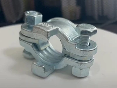
Ferrule: steel plated ferrule
Key Advantage of PVC-Nitrile layflat hose: Flat-roll storage, compact transportation; bIt provides better oil and chemical resistance than a conventional PVC layflat hose and resists kinking and twisting during liquid transfer.
Check hose end: Cut hose end squarely with sharp cutter; reject jagged, oblique or cracked hose end segment (max damaged cutting segment cut off). For cold rigid hose end, soak in 60-70℃ hot water for 30 60 seconds to soften tube wall for easier shank insertion, avoid forced prying which may cause inner-layer delamination。
Inspect camlock parts: Check coupling shank barbs for burr, crack or deformation; verify cam arm spring works normally; examine female coupler gasket for aging, crack or offset displacement, replace defective gasket before assembly。
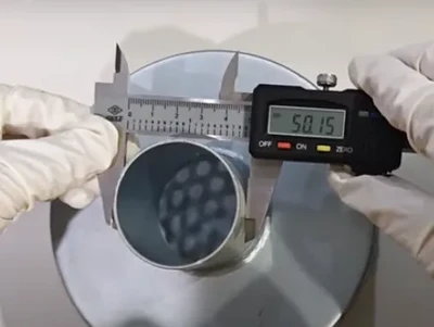
Size matching: Camlock barb-shank nominal inner diameter must strictly match hose inner diameter. Mismatched dimension is the top cause for pull out risk and joint leakage。
Fully push hose onto barbed shank until hose end passes all barb ridges, ensure complete seating without gap between hose inner bore and shank surface。
Position steel plated ferrule above the hose. Crimp ferrule with controlled torque, DO NOT over-tighten — excessive torque will crush and damage the PVC-Nitrile hose wall, resulting in early failure.
For camlock inter connection: Fully open two cam arms first; insert male adapter into female coupler, simultaneously press down both cam arms until “click-lock” in place, ensure both arms fully engaged without loose play. Never operate camlock under system pressure。
Fault Phenomenon | Root Cause | Corrective Action |
Joint seepage under pressure | Gasket aging/deformation; hose not fully seated; single-sided cam-arm locking; wrong size matching | Replace gasket; re-push hose to full barb coverage; lock two cam arms simultaneously; verify ID matching |
Hose slip / pull out from shank | Incomplete insertion; insufficient ferrule torque; crimp dimension out-of-spec | Re-assemble to full insertion depth; adjust ferrule torque; re-crimp per factory specification |
Hose end crack after assembly | Over-tight ferrule torque; cold hard hose forced assembly without softening | Reduce tightening torque; soak hose-end in hot water before fitting |
Unless specifically designed and approved for the application, camlock couplings should not be used for steam, compressed air, or liquefied gas service. Always confirm the coupling material, gasket compatibility, and pressure rating before use.
Fully depressurize the entire hose assembly before connecting or disconnecting the camlock coupling.
For long-term storage, disconnect the coupling and keep the cam arms in the unlocked position to avoid prolonged compression of the gasket. Store the hose assembly away from direct sunlight, ozone sources, and sharp objects that could puncture or damage the hose.